

How Biorefinery Systems Process Olive Mill Water
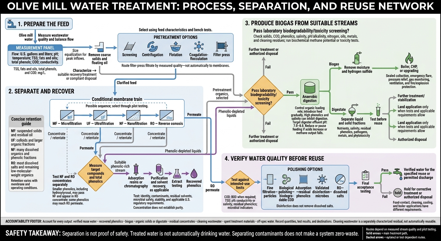
I break olive mill water treatment into three goals: recover phenolics, produce biogas, and prepare water for tested reuse. The first step is to measure the wastewater and remove solids and oil - not send everything straight to membranes or a digester.
Here’s the treatment path I outline:
- Prepare the feed: Balance flow and remove materials that can clog equipment.
- Separate and recover: Use membranes to split the liquid, then purify suitable phenolic-rich streams.
- Produce biogas: Send only lab-screened organic streams to digestion. High phenolic levels can slow or stop the process.
- Check every output: Test digestate, polish water for its intended use, and track solids, cleaning waste, and leftover concentrates.
My bottom line: <u>separation is not proof of safety</u>. Recovered extracts, water, and digestate each need testing before use. And treated water is not automatically drinking water.
Olive Mill Water Treatment: Recovery, Biogas, and Reuse
Olive mill waste (OMW) management
sbb-itb-4066b8e
Prepare Olive Mill Water for Separation
Before membrane separation, stabilize the feed and remove solids and oil that can foul the membranes.
Measure Wastewater Quality and Balance Flow
Use a calibrated flow meter to log daily and hourly wastewater volumes in U.S. gallons and liters. Record milling hours and wash-water use as well.
Collect composite samples during startup, peak production, routine operation, and shutdown. Measure pH and temperature when collecting samples. Test total suspended solids (TSS), fats and oils, total phenols, and chemical oxygen demand (COD) in mg/L. COD indicates the organic pollution load. Record conductivity separately to track dissolved salts.
Size the covered equalization tank for peak inflows, not just seasonal averages. Include gentle mixing, level alarms, overflow protection, odor control, and a controlled feed pump. Keep mixing gentle enough to avoid emulsifying oil. Use average and peak test results to set equipment capacity and acceptable feed conditions.
Remove Coarse Solids and Floating Oil
Select equipment based on particle size, TSS, oil content, and settling behavior. Check the proposed treatment sequence with settling, jar, or centrifuge tests before full-scale operation. Suspended particles, fats, and pectins can foul membranes, so clear-looking liquid doesn't prove that pretreatment is adequate.
| Separation method | Input | Purpose | Outputs |
|---|---|---|---|
| Screening | Leaves, pits, fibers, and coarse debris | Protect pumps and downstream equipment | Screenings and screened liquid |
| Centrifugation | High-TSS wastewater or dense organic solids | Separate suspended solids and heavier particles at speed | Clarified liquid and wet organic solids |
| Flotation | Wastewater containing free oil, fats, and light suspended particles | Lift low-density material for skimming | Clarified liquid, separated fats, and float sludge |
| Coagulation-flocculation | Fine colloids, emulsified oil, and poorly settling particles | Group small particles so they can be removed | Flocculated solids and clarified liquid |
| Filter press | Concentrated sludge or flocculated solids | Dewater solids and reduce handling volume | Filter cake and filtrate |
Each pretreatment step helps reduce fouling risk and maintain a consistent feed for downstream separation.
Jar-test the coagulant before full-scale use, and document every chemical addition. Coagulation can improve solids removal while increasing conductivity, so track both measures. During operation, inspect screens, check for oil carryover, and monitor TSS or turbidity and pressure differential. Rising pressure can signal inadequate pretreatment.
Track clarified liquid, fats, and solids separately. Before digestion, composting, or compliant disposal, assess screenings, sludge, and filter cake for moisture, phenols, salinity, organic content, and contaminants. Route filter-press filtrate according to its measured quality - don't send it to membranes by default. The clarified feed then moves into membrane separation for phenolic recovery.
Filter the Liquid and Recover Phenolics
After screening and oil removal, the clarified feed enters membrane separation.
Separate Permeate from Concentrate
Membranes split the clarified feed into permeate and concentrate (retentate). Microfiltration (MF), ultrafiltration (UF), nanofiltration (NF), and reverse osmosis (RO) may run in sequence. The separation path depends on membrane cutoff, feed chemistry, pH, temperature, pressure, crossflow, and pretreatment. Do not assume fixed recoveries or complete compound separation.
Use pilot testing to set pressure, crossflow, temperature, and pH. Higher pressure may increase flux at first, but it can also worsen concentration polarization and fouling. Higher crossflow can reduce the deposit layer, though it uses more pumping energy.
Track normalized permeate flux, pressure drop, conductivity, COD or total organic carbon, and phenolics. Stay within the membrane manufacturer’s cleaning limits, and check performance recovery after cleaning. Collect and characterize cleaning wastewater separately.
Concentrate and Purify Phenolics
Test NF and RO concentrates separately before choosing a stream for phenolic recovery. NF may retain larger phenolic fractions, while smaller compounds, such as hydroxytyrosol, can pass through NF and appear later in RO concentrate. Some phenolics may also reach the RO permeate. Measure both target compounds and total phenolics: concentration alone does not establish purity.
Adsorption resins or chromatography can separate phenolics from other dissolved material. Resin processing can use ethanol to release the retained compounds, followed by vacuum evaporation to recover the solvent. Optional membrane distillation can further concentrate suitable fractions if heat integration and vapor control are available.
Before using an extract in food, assess its identity, contaminants, residual solvents, microbial safety, stability, and applicable U.S. regulatory requirements.
Track Membrane Outputs and Destinations
Treat the table as a routing guide, not an approval for use. Record feed, permeate, and concentrate flows at each stage. During steady operation, check that feed flow approximately equals the combined output flows. Keep laboratory results linked to each stream before approving recovery, digestion, or reuse.
| Membrane stage | Typically retained compounds | Permeate destination | Concentrate destination | Recovery objective |
|---|---|---|---|---|
| MF | Suspended solids, residual oil droplets, biomass | UF feed after quality testing | Solids handling or digestion if biodegradable | Protect downstream membranes and remove particulates |
| UF | Colloids, emulsions, proteins, polysaccharides, larger organic fractions | NF feed after quality checks | Phenolic recovery or blending for digestion after screening | Reduce fouling load and fractionate organic matter |
| NF | Many dissolved organic compounds and phenolic fractions; retention varies by membrane and operating conditions | RO feed or reuse assessment | Adsorption, chromatography, further concentration for phenolic recovery, or digestion if suitable | Enrich recoverable phenolics while producing a cleaner permeate |
| RO | Most dissolved salts and remaining low-molecular-weight organics, including potentially hydroxytyrosol | Reuse testing | Phenolic recovery, controlled digestion, or permitted disposal | Produce polished water and retain dissolved organics |
Concentrates that fail recovery criteria go to digestion or disposal based on measured phenolics, salinity, biodegradability, and chemical residues. Route streams that are too dilute, salty, or phenolic-rich for recovery to digestion only after lab screening.
Digest Suitable Organic Streams for Biogas
When streams are no longer suitable for phenolic recovery, send them to energy recovery through anaerobic digestion, which converts organic material into biogas. Only route pretreatment solids, membrane concentrates, and phenolic-depleted liquids that pass lab screening.
Prepare Feed and Limit Microbial Inhibition
Measure total and volatile solids (TS and VS), total and soluble COD, total phenolics, pH, alkalinity, salinity, ammonia, total Kjeldahl nitrogen (TKN), oil and grease, and relevant metals and cleaning residues. Run laboratory biochemical methane potential or toxicity tests. Compare methane production, lag time, and COD removal against a control substrate.
Equalize the feed, adjust pH and alkalinity, and introduce it gradually. Control the organic loading rate - not just the flow. High salinity and overfeeding can disrupt methanogens and cause volatile fatty acids to build up.
Track pH, alkalinity, volatile fatty acids (VFAs), methane production, COD, and loading rate. Target a digester effluent pH of 7.0–8.0. Reduce or pause feeding if acids increase or methane output falls. Don't wait for pH to drop.
Collect Biogas and Treat Digestate
Biogas consists mostly of methane and carbon dioxide, with water vapor and hydrogen sulfide. Collect it in a sealed system with condensate removal, an emergency flare, pressure relief, gas monitoring, ventilation, and fire/explosion protection. Remove moisture and hydrogen sulfide before sending the gas to a boiler, combined heat and power (CHP) unit, or upgrading system.
After biogas recovery, use test results to decide where digestate goes next. Leaving the reactor doesn't mean it's ready for reuse. Separate and track the liquid and solid fractions using screening, pressing, or centrifugation as needed. Before reuse, test digestate for nutrients, salinity, residual phenolics, pathogens, metals, and phytotoxicity.
Liquids may need further biological treatment or polishing. Solids may need dewatering, stabilization, or composting. Allow land application only when test results, agronomic limits, and applicable federal, state, and local requirements support it. Otherwise, send digestate for further treatment or authorized disposal.
Verify Water Quality Before Reuse
Measure success by final water quality - not treatment steps alone. Reuse water is one output of the biorefinery system. Set reuse limits before the system starts running, then test the final water for COD, BOD when required, TSS, pH, conductivity or salinity, residual phenolics, and microbial indicators. Record limits, sampling frequency, results, and corrective actions. Once the stream meets its target route, polish it to meet the exact reuse or discharge standard.
Polish Water for Its Intended Use
Choose polishing steps based on the contaminants still in the water. Use fine filtration for particles, biological polishing for remaining biodegradable COD, and adsorption for residual phenolics. Add validated disinfection for microbes and reverse osmosis for dissolved salts when needed. Disinfection does not remove dissolved salts. Hold water that fails acceptance criteria and send it for corrective treatment or authorized disposal.
For cleaning systems, check hardness and scaling risk. For cooling or boiler use, also check silica and corrosion risk. Olive-wash water must meet food-contact water requirements. Confirm reuse and discharge limits with the relevant environmental, sewer, and food-safety authorities. Federal, state, and local requirements vary by application.
Conclusion: Account for Every Output
After polishing, record where each stream goes. Track quantities, test results, and destinations separately for verified reuse water, recovered phenolics, biogas, organic solids or digestate, and residual concentrates. Include spent treatment materials and off-spec water in these records. Concentrates still need recovery, treatment, or authorized disposal.
Choose the process train based on wastewater composition, seasonal volume, mill equipment, recovery goals, and intended reuse. Recovered water is not automatically potable, and separating contaminants does not make a system zero-waste.
FAQs
Can small olive mills afford biorefinery treatment?
High upfront costs can put biorefinery treatment out of reach for small olive mills. But long-term savings and revenue from recovered phenols, biogas, and biofertilizers may help offset the initial expense.
Simpler treatment methods, treatment introduced in stages, or cooperative models can make costs easier to afford. Whether an approach is feasible depends on weighing startup costs against long-term running costs, savings, byproduct revenue, and compliance requirements.
How does seasonal production affect biogas recovery?
Seasonal wastewater supply can lead to biomass loss, forcing operators to restart systems each year. During peak harvest, wastewater volumes and pollutant concentrations climb. Phenolic compounds, in particular, can inhibit microbes and acidify reactors, putting methane production at risk.
To keep biogas yields steady, operators use equalization tanks, increase loading gradually, or co-digest wastewater with other agricultural by-products. Upflow Anaerobic Sludge Blanket (UASB) reactors are favored because they remain effective after idle periods.
Which water reuse options need the least treatment?
Tasks like washing olives and cleaning equipment generally need the least water treatment. Nanofiltration can remove suspended solids and oils from mill wash water and vegetation water so the water can be used for these tasks.
Irrigation, environmental discharge, and high-purity applications need more intensive treatment, such as membrane sequences or biological polishing.